
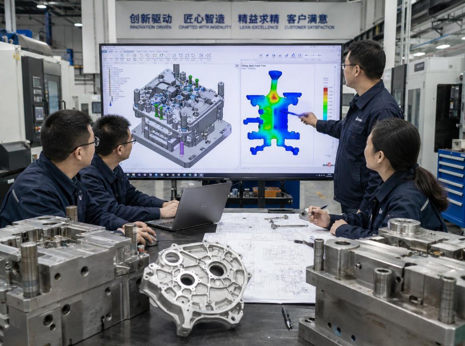
A successful die casting project starts with the right design decisions before tooling begins.
Optimizing part geometry during the initial CAD stage is one of the most effective ways for OEM engineers to reduce production risks, control tooling costs and improve casting quality.
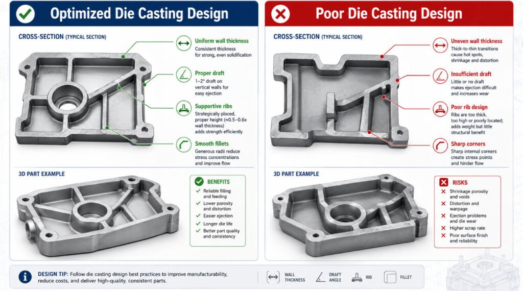
The key principles of high-quality die casting design include:
- Uniform wall thickness
- Proper draft angles
- Strategic rib placement
- Fillet and radius optimization
- Parting line planning
- Metal flow considerations
Poor design decisions can lead to costly production issues, including:
- Internal porosity
- Shrinkage cavities
- Cold shuts
- Warping
- Additional tooling modifications
At FSD Precision, we work with OEM engineering teams during the early design stage to provide Design for Manufacturability (DFM) feedback and manufacturing guidance.
Our support includes:
- Die casting design review
- Tooling coordination
- CNC post-machining
- Surface finishing
- Quality inspection
Learn more about our Custom Die Casting Services.
Why Die Casting Design Matters
High-pressure die casting (HPDC) forces molten metal into a steel mold at high speed and pressure.
Because filling and solidification happen within a very short cycle, even small design problems can affect:
- Metal flow
- Cooling balance
- Dimensional stability
- Final part quality
A DFM-optimized die casting design helps achieve:
Optimized Metal Flow
Proper geometry allows molten metal to fill the mold cavity smoothly while reducing:
- Trapped air
- Incomplete filling
- Turbulent flow
Good metal flow design helps improve casting consistency and reduce defect risks.
Lower Defect Risk
Good design practices help minimize:
- Porosity
- Shrinkage
- Cold shuts
- Surface defects
Many casting defects are not caused by the machine itself, but by design decisions made before tooling.
Longer Tool Life
Optimized designs reduce:
- Thermal stress
- Metal erosion
- Excessive wear on mold components
A well-designed part helps improve mold stability and production efficiency.
Lower Manufacturing Cost
A good design can reduce:
- Tool modifications
- Scrap rates
- Production delays
- Secondary correction work
For OEM buyers, early DFM review is one of the most effective ways to control total project cost.
The Core Design Principles of High-Yield Die Casting
1. Wall Thickness: Keep It Uniform
Wall thickness is one of the most important factors in die casting design.
During casting, molten metal cools and solidifies at different speeds.
When a design contains sudden transitions between thin and thick sections, it may create:
- Internal shrinkage
- Porosity
- Surface sink marks
- Uneven cooling stress
Recommended Approach
Maintain consistent nominal wall thickness throughout the component whenever possible.
If additional strength is required, avoid simply adding more material thickness.
Instead, consider:
- Structural ribs
- Better geometry design
- Proper fillets
This improves stiffness while reducing casting risks.
2. Draft Angles: Improve Mold Release
Draft angles allow the finished part to release from the mold more easily.
Without sufficient draft:
- Ejection forces increase
- Surface damage may occur
- Mold wear can accelerate
- Production efficiency decreases
Draft requirements depend on:
- Material selection
- Part depth
- Surface finish
- Mold structure
Adding draft angles during the design stage improves tooling reliability and production consistency.
3. Ribs and Fillets: Improve Strength and Metal Flow
Structural Ribs
Ribs increase stiffness without significantly increasing wall thickness.
They help:
- Improve structural strength
- Reduce deformation
- Maintain lightweight designs
Common applications:
- Housings
- Covers
- Structural brackets
Fillets and Radii
Sharp internal corners can create:
- Poor metal flow
- Stress concentration
- Increased defect risk
Proper radii help:
- Smooth metal flow paths
- Reduce stress concentration
- Improve part reliability
For die casting, rounded transitions are generally preferred over sharp internal corners.
Managing Parting Lines and Casting Defects
The parting line is where two halves of the steel mold meet.
Its position affects:
- Flash location
- Appearance
- Machining access
- Finishing requirements
Proper parting line planning helps improve:
- Tool design
- Trimming efficiency
- Cosmetic quality
Common Die Casting Defects and Design Solutions
| Defect | Common Cause | DFM Solution |
|---|---|---|
| Porosity | Trapped air or uneven solidification | Optimize metal flow, venting and gate design |
| Shrinkage | Thick sections cooling unevenly | Maintain consistent wall thickness |
| Cold Shuts | Poor metal flow connection | Improve filling direction and gate location |
| Warping | Uneven cooling stress | Balance structure and cooling conditions |
| Flash | Mold mismatch or pressure issues | Improve tooling design and clamping accuracy |
Understanding these risks before tooling begins helps prevent expensive production changes.
Mold Flow Analysis and DFM Review
Before mold manufacturing, engineers should evaluate how molten metal behaves inside the cavity.
Mold flow analysis helps review:
- Filling behavior
- Metal temperature
- Air trap risks
- Cooling performance
- Potential defect areas
Early DFM review can reduce:
- Tool modifications
- Trial-and-error adjustments
- Production delays
Designing for CNC Post-Machining
Many die cast parts require CNC machining after casting.
Die casting is excellent for producing near-net-shape components, but some features require additional machining for functional requirements.
Typical CNC post-machining operations include:
- Precision holes
- Internal threads
- Bearing bores
- Assembly surfaces
- Critical tolerance features
Machining Allowances
Reserve additional material on surfaces that require precision machining.
The required allowance depends on:
- Part geometry
- Casting condition
- Final tolerance requirements
Stable Machine Datums
Design reliable reference surfaces or locating features to ensure repeatable CNC fixturing.
Critical Features
Identify areas requiring:
- Tight dimensional control
- Assembly accuracy
- Sealing performance
FSD Precision combines die casting with CNC machining services to complete precision features after casting.
Die Casting Design vs CNC Machining Design
Die casting and CNC machining require different design approaches.
Although both processes can produce high-quality metal components, the design mindset is completely different.
| Design Factor | Die Casting | CNC Machining |
|---|---|---|
| Main consideration | Metal flow and mold release | Tool access and material removal |
| Important features | Draft angles, wall thickness, parting lines | Tool radius, machining access, fixture design |
| Best for | Medium/high-volume production | Prototype and low-volume parts |
| Main cost driver | Tooling investment | Machine time and material removal |
For die casting, engineers focus on:
- How molten metal fills the cavity
- How the part releases from the mold
- How cooling affects dimensional stability
For CNC machining, engineers focus on:
- Tool accessibility
- Cutting paths
- Material removal efficiency
- Fixture stability
Choosing the correct manufacturing process early can significantly influence project cost, lead time and production reliability.
How to Choose the Right Die Casting Manufacturer
Selecting a die casting supplier requires more than checking whether a company owns casting equipment.
A reliable OEM manufacturing partner should provide engineering support throughout the entire production process.
DFM Engineering Support
A capable supplier should help review:
- Part geometry
- Material selection
- Metal flow risks
- Potential casting defects
- Secondary machining requirements
Early engineering involvement helps identify issues before tooling production begins.
Tooling Capability
Tooling quality directly affects long-term production stability.
Important factors include:
- Mold design experience
- Tool maintenance capability
- Cooling system design
- Production support
A well-designed mold helps improve:
- Part consistency
- Tool life
- Production efficiency
CNC and Secondary Processing Capability
Many die cast parts require additional operations after casting.
Common processes include:
- CNC machining
- Drilling
- Tapping
- Milling
- Surface finishing
Working with a supplier that integrates casting and post-machining can simplify communication and improve quality control.
FSD Precision supports customers with integrated CNC machining services after die casting.
Surface Finishing Capability
Many OEM parts require additional finishing for:
- Appearance
- Corrosion resistance
- Functional performance
Common finishing options include:
- Powder coating
- Painting
- Sand blasting
- Plating
- Chemical treatments
Learn more about our Surface Finishing Services.
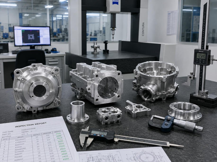
Inspection Capability
Quality control should include:
- Dimensional inspection
- CMM measurement
- Material verification
- Production documentation
A reliable supplier should be able to verify that finished components meet engineering requirements before shipment.
Why Choose FSD Precision for Die Casting Projects?
FSD Precision supports OEM customers with complete manufacturing solutions from initial design review to final production delivery.
Our engineering team helps customers evaluate:
- Part design
- Manufacturing feasibility
- Material selection
- Production volume
- Tolerance requirements
- Surface finishing needs
Our capabilities include:
- Die casting project evaluation
- Aluminum and zinc die cast parts
- Tooling coordination
- CNC post-machining
- Surface finishing
- Quality inspection
- Export support
Instead of simply producing cast components, we help customers develop reliable manufacturing processes from concept through production.
Unlock a Professional DFM Review for Your Die Casting Project
A small design issue discovered after tooling production can lead to:
- Mold modification costs
- Production delays
- Additional machining requirements
- Increased manufacturing expenses
Working with an engineering-focused manufacturing partner early in the design stage helps reduce these risks.
Submit your:
- 3D CAD files
- 2D drawings
- Material requirements
- Production quantities
- Surface finish requirements
to FSD Precision for engineering evaluation and quotation.
👉 Contact FSD Precision to Start Your Die Casting Project
Frequently Asked Questions (FAQ)
What is DFM in die casting?
DFM (Design for Manufacturing) is the engineering process of optimizing a component’s design before production to improve manufacturability, reduce defects and control manufacturing costs.
A proper DFM review considers:
- Wall thickness
- Draft angles
- Metal flow
- Tool accessibility
- CNC machining requirements
What wall thickness is recommended for die casting?
Wall thickness depends on:
- Material
- Part size
- Geometry
- Production requirements
The most important principle is maintaining consistent wall thickness and avoiding sudden transitions between thin and thick areas.
Why are draft angles needed in die casting?
Draft angles allow parts to release from the mold smoothly.
They help reduce:
- Ejection problems
- Surface damage
- Mold wear
Proper draft design improves production efficiency and tooling reliability.
How can die casting defects be reduced?
Common methods include:
- Maintaining uniform wall thickness
- Using proper draft angles
- Optimizing metal flow
- Performing mold flow analysis
- Improving venting and overflow design
- Reviewing designs before tooling
Does FSD Precision provide die casting design review?
Yes.
FSD Precision supports OEM customers with:
- DFM feedback
- Tooling coordination
- CNC post-machining
- Surface finishing
- Quality inspection
What information should I provide for a die casting design review?
For a complete engineering review, customers should provide:
- 3D CAD files
- 2D engineering drawings
- Material requirements
- Production quantity
- Critical tolerances
- Surface finish expectations
Before starting your project, you can also review our:
How early should DFM review start in a die casting project?
DFM review should begin during the CAD design stage, before tooling production.
Early review helps identify:
- Wall thickness issues
- Metal flow problems
- Draft angle requirements
- CNC machining considerations
This reduces tooling risks and improves production stability.
Conclusion
Great die casting components are not created only during production. They are engineered correctly before the mold is manufactured.
By optimizing:
- Wall thickness
- Draft angles
- Ribs
- Fillets
- Parting lines
- CNC machining requirements
OEM engineering teams can reduce defects, control tooling costs and improve production stability.
FSD Precision helps customers optimize die casting projects from initial design review through:
- Tooling
- Casting
- CNC post-machining
- Surface finishing
- Final inspection
If you are developing a new die casting component, our engineering team can help evaluate your design and recommend a practical manufacturing solution.
👉 Send your CAD files and project requirements to FSD Precision for engineering review and quotation.
Need help sourcing custom OEM parts?
Send drawings, samples, part numbers, material requirements, quantity, and application details for engineering review.