
Repeat Production
Stamping may be reviewed when repeated quantities can support tooling and process planning.
METAL STAMPING
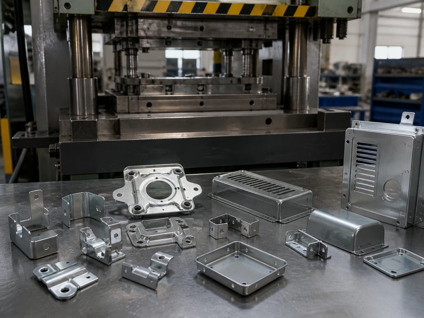
FSD supports custom metal stamping for brackets, covers, clips, shields and formed components, from drawing and tooling review to repeat production, secondary operations and finishing.
BUYER DECISION
Metal stamping is usually reviewed when the part geometry, material form, quantity and tooling plan support a repeatable sheet-metal manufacturing route.
Stamping may be reviewed when repeated quantities can support tooling and process planning.
Flat, bent, pierced or formed sheet geometries are common starting points for stamping review.
Tooling strategy should be compared with quantity, revision risk and long-term production needs.
Deburring, tapping, bending, welding, finishing and inspection should be considered early.
PROCESS OPTIONS
Different stamping routes should be reviewed against geometry, quantity, tooling, finish and downstream operations instead of selected by process name alone.
Useful for selected features or simpler formed parts where a focused tooling approach fits the project.
May be reviewed for repeat production when multiple forming or piercing steps can be planned in sequence.
Many stamped parts require planned deburring, tapping, bending, welding, finishing or inspection after stamping.
Final stamping route depends on drawing requirements, material, geometry, quantity and production plan.
STAMPING MATERIALS
Material selection should be reviewed with thickness, bend geometry, surface protection, conductivity needs and production requirements.
| Material | Typical Review Focus | Related Material Guide |
|---|---|---|
| SPCC / SECC | Sheet-based carbon steel parts, surface protection, forming behavior and coating requirements. | Carbon Steel Material Guide |
| Stainless Steel 304 | Corrosion exposure, formed geometry, surface condition and drawing-critical interfaces. | Stainless Steel Material Guide |
| Aluminum Sheet | Lower weight, selected formed geometry, surface finish and application requirements. | Aluminum Material Guide |
| Copper Alloy Strip | Conductive function, connector features, formed details and surface requirements. | Copper & Brass Material Guide |
DFM CHECKLIST
Stamped part design should be reviewed before tooling so material behavior, bends, pierced features and inspection points are clear.
View Design GuidelinesMaterial Thickness
Material thickness affects forming behavior, tooling review and feature feasibility.
Bend Geometry
Bend radius, flange geometry and nearby features should be reviewed together.
Hole-to-Edge / Hole-to-Bend Relationships
Hole location should be reviewed against edges, bends and formed features.
Burr Direction
Define burr direction where assembly, handling or contact surfaces matter.
Flatness & Springback
Flatness expectations should consider material behavior, geometry and forming sequence.
Critical Interfaces
Datums, mounting holes and mating features should be identified before tooling review.
TOOLING PLAN
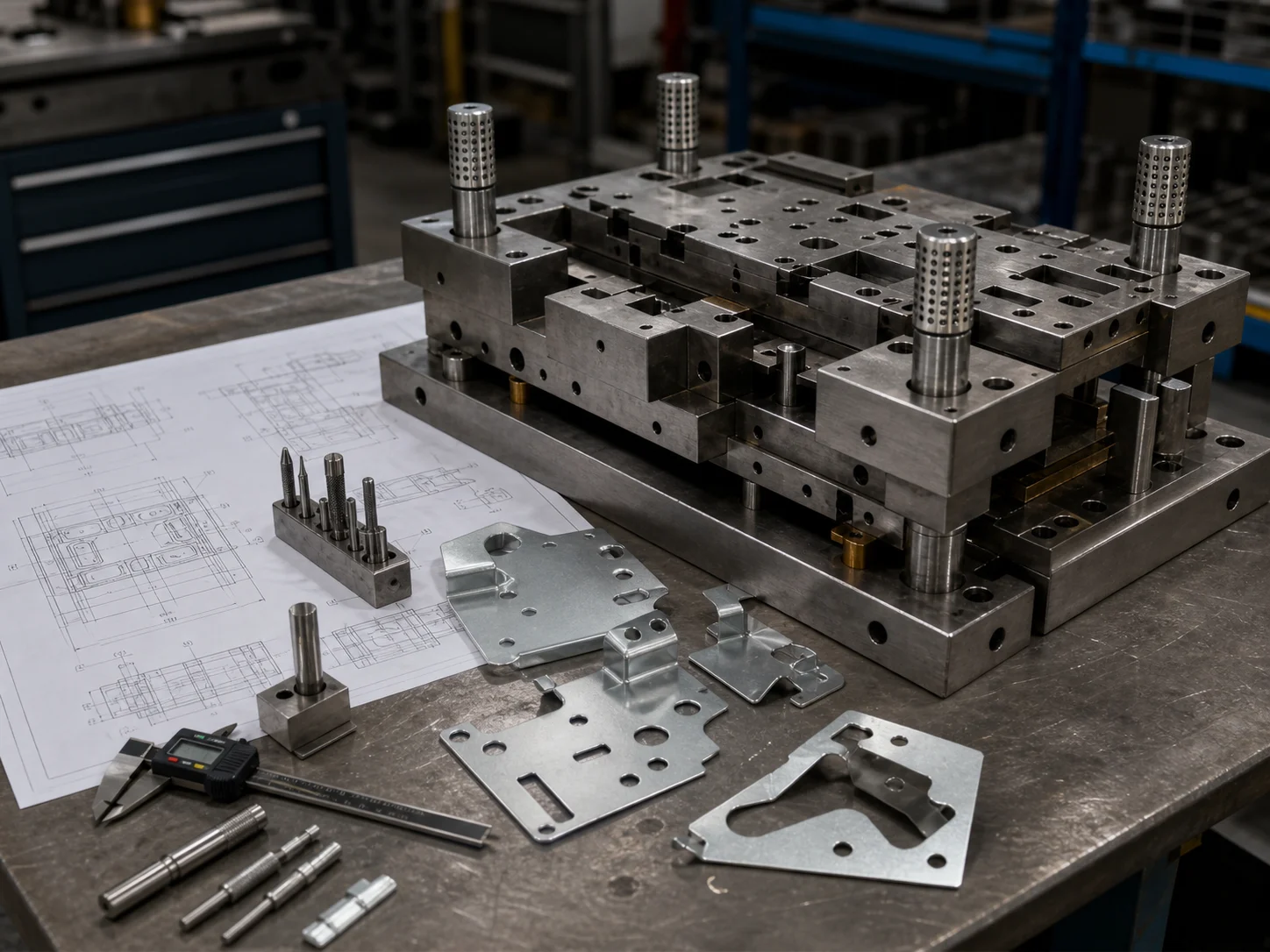
Tooling strategy should be reviewed against geometry, volume, tolerance, revision risk and the production plan before moving from early validation into repeat production.
Review geometry, material, interfaces and revision risk before committing to a production tooling route.
Confirm formed features, critical dimensions, downstream operations and inspection needs.
Align tooling, process flow, quality checks and finishing expectations for repeated orders.
Evaluate whether a progressive route fits the part geometry, volume and long-term production plan.
STAMPED PARTS
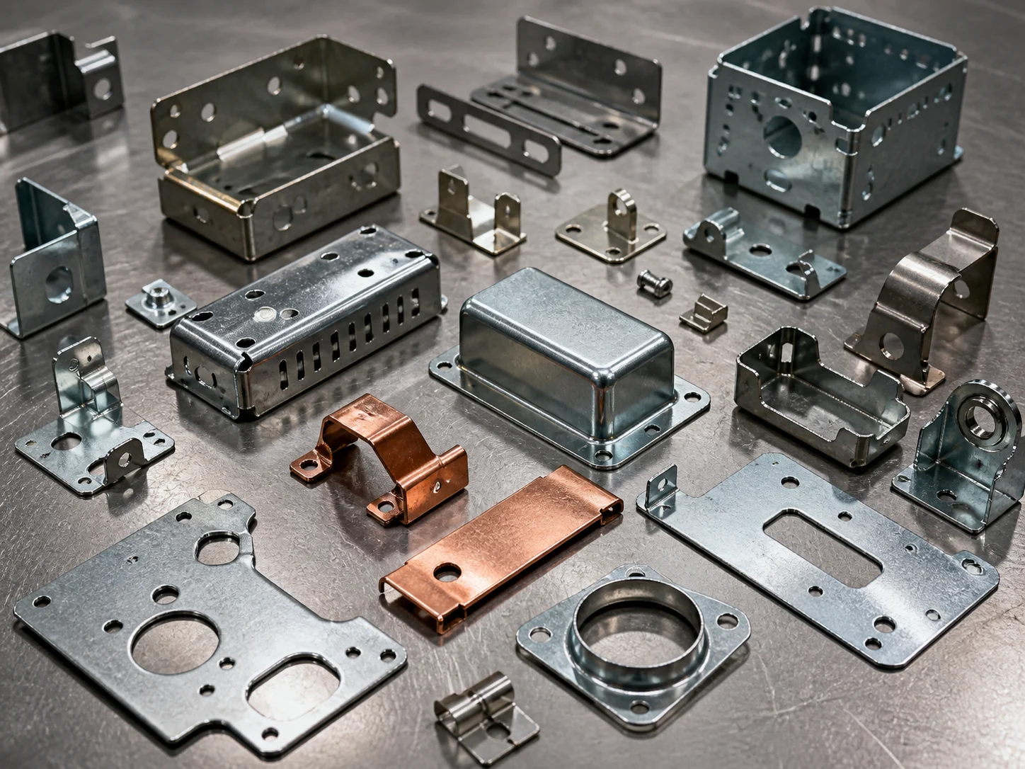
Stamped metal parts often combine flat profiles, pierced features, bends, formed areas and secondary operations depending on the drawing.
Bends, mounting holes and assembly interfaces.
Formed edges, openings and appearance surfaces.
Small formed features, spring behavior and handling edges.
Thin sheet geometry, openings and assembly features.
Hole locations, flatness and critical mounting interfaces.
Multiple bends, flanges and load-related geometry.
DOWNSTREAM WORKFLOW
Stamped components may require planned secondary operations before final inspection and delivery. The sequence should be reviewed with drawing and surface requirements.
QUALITY CONTROL
Inspection requirements should follow the drawing, datums, critical features and project requirements instead of a generic checklist.
Profile and outline features should be checked against drawing requirements.
Bend angles should be reviewed with material behavior, tooling and inspection method.
Hole position and interfaces should follow datums and functional assembly needs.
Flatness expectations should be reviewed with material, geometry and forming sequence.
Burr direction and edge requirements should be defined for function and assembly.
Surface and coating checks should reflect drawing, finish and application requirements.
PROCESS COMPARISON
Use this table to compare early process fit. It is not a ranking of better or worse processes.
| Factor | Metal Stamping | CNC Machining | Sheet Metal Fabrication | Die Casting |
|---|---|---|---|---|
| Typical Geometry | Sheet-based profiles, bends and formed features. | Machined features from billet, plate or bar stock. | Cut, bent and assembled sheet metal structures. | Cast geometry with tooling-defined features. |
| Tooling | Stamping tooling is reviewed against quantity and geometry. | Usually fixture and machining setup focused. | May use forming tools, fixtures and welding aids. | Die casting tooling is central to the process. |
| Repeat Volume | Often reviewed where repeat production can support tooling. | Flexible for prototypes, low-volume and precision work. | Common for sheet assemblies and enclosures. | Often reviewed for repeat casting projects. |
| Secondary Operations | Deburring, tapping, bending, welding, finishing and inspection may be planned. | Finishing, deburring, inspection and assembly may follow machining. | Welding, hardware insertion, finishing and assembly may be involved. | Trimming, deburring, machining and finishing may follow casting. |
| Material Form | Sheet or strip material. | Block, plate, bar or plastic stock. | Sheet metal material. | Castable alloy material. |
| Best Review Focus | Thickness, bends, holes, burrs, tooling and production plan. | Tolerances, features, tool access, material and setup. | Cutting, bending, joining, finish and assembly. | Parting, draft, wall thickness, tooling and post-processing. |
PRODUCTION PATH
A practical stamping project should connect drawing review, process planning, sampling, inspection and finishing before repeat production.
Drawing Review
Process / Tooling Review
Sample / Pilot
Inspection
Repeat Production
Finishing / Delivery
FAQ
Metal stamping is a manufacturing process that uses tooling and press force to cut, pierce, bend or form sheet metal into custom parts.
Metal stamping may be a good choice when the part uses sheet material, has repeatable geometry and the expected production plan can justify tooling review.
Commonly reviewed materials include SPCC, SECC, stainless steel 304, aluminum sheet and copper alloy strip, depending on thickness, geometry and application requirements.
Single-operation stamping uses a focused operation for selected features or parts, while progressive stamping can combine multiple steps in sequence for suitable repeat production projects.
Yes. Stamped parts may include secondary operations such as tapping, bending, spot welding, deburring, surface finishing and inspection when required by the drawing.
Include drawings, material, thickness, quantity, critical dimensions, surface finish, annual volume and any assembly or inspection requirements.
Stamped parts are inspected against drawing requirements, including profile accuracy, bend angle, hole location, flatness, burr direction and surface or coating requirements.
Stamping should be reviewed when sheet-based geometry, repeat quantity, tooling economics and downstream operations fit the project better than a machined or fabricated route.
RFQ PREPARATION
Share the drawing, material, thickness, quantity, critical dimensions, surface finish and annual volume so the stamping route, tooling approach and secondary operations can be reviewed together.