
Trust & Quality Assurance
✓ ISO 9001:2015 Certified Manufacturing Partner
✓ Pre-Tooling DFM Review for OEM Projects
✓ Mold Flow Analysis & Process Optimization
✓ CNC Post-Machining & CMM Inspection Support
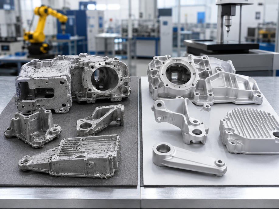
Direct Answer: What Are the Main Die Casting Defects?
The most common aluminum die casting defects include:
- Porosity
- Shrinkage cavities
- Cold shuts
- Flash
- Warping
- Surface defects
These defects are usually caused by:
- Poor part design
- Improper mold design
- Unstable metal flow
- Uneven cooling
- Incorrect process parameters
For OEM manufacturers, preventing defects before production is far more effective than correcting problems after tooling is completed.
High-quality die casting requires:
- Design for Manufacturability (DFM)
- Mold flow analysis
- Proper tooling design
- Stable process control
- CNC post-machining
- Quality inspection
FSD Precision helps OEM customers identify potential risks early and develop reliable die casting solutions from engineering review to final inspection.
Explore our:
Why Die Casting Defects Happen
High-pressure die casting (HPDC) fills a steel mold cavity with molten metal at extremely high speed and pressure.
Because filling and cooling occur within seconds, small problems in design or process control can affect final part quality.
Common risk factors include:
- Non-uniform wall thickness
- Trapped gases
- Poor metal flow
- Incorrect venting
- Cooling imbalance
- Tool wear
- Unstable injection parameters
Many defects can be prevented before tooling production through proper engineering evaluation.
For design optimization, review:
Common Die Casting Defects and Prevention Methods
| Defect | Main Cause | Prevention Method | OEM Impact |
|---|---|---|---|
| Porosity | Trapped gas or uneven solidification | Improve venting, metal flow and tooling design | Leakage, reduced strength |
| Shrinkage | Uneven cooling and thick sections | Improve wall thickness and cooling balance | Internal weakness |
| Cold Shut | Poor fusion between metal flow fronts | Optimize gating and injection parameters | Reduced structural reliability |
| Flash | Mold mismatch or excessive pressure | Improve tooling accuracy and maintenance | Extra finishing cost |
| Warping | Thermal stress during cooling | Balance design and cooling conditions | Assembly issues |
1. Porosity in Aluminum Die Casting
Porosity is one of the most critical quality concerns in aluminum die casting.
It refers to internal voids or gas pockets formed inside the casting.
Porosity can affect:
- Mechanical strength
- Pressure tightness
- Sealing performance
- Machining reliability
For applications such as:
- Automotive components
- Hydraulic housings
- Pressure-sensitive parts
porosity control is essential.
Learn more:
Gas Porosity
Gas porosity occurs when air or gas becomes trapped during metal filling and solidification.
Common causes:
- Poor mold venting
- Excessive turbulence
- Incorrect injection parameters
Prevention methods:
- Improve venting systems
- Optimize gate design
- Control filling speed
- Use mold flow analysis
Shrinkage Porosity
Shrinkage porosity occurs when molten metal contracts during cooling but cannot properly feed the shrinking area.
Common causes:
- Thick sections
- Uneven wall thickness
- Poor cooling balance
Prevention methods:
- Improve part geometry
- Optimize cooling design
- Maintain consistent wall thickness
Vacuum-Assisted Die Casting for Critical Applications
For demanding OEM applications, vacuum-assisted die casting can help reduce gas entrapment and improve internal casting quality.
It is often considered for:
- Pressure-sensitive components
- High-reliability parts
- Applications requiring improved internal consistency
Porosity Inspection Methods
For critical components, manufacturers may use:
- X-ray inspection
- CT scanning
- Leak testing
- Section analysis
The inspection method depends on:
- Part function
- Pressure requirements
- Customer specifications
2. Shrinkage Defects
Shrinkage defects are usually caused by uneven solidification.
They commonly appear in:
- Thick sections
- Heavy bosses
- Poorly designed transitions
Manufacturers reduce shrinkage risks through:
- Better part geometry
- Balanced cooling
- Proper tooling design
3. Cold Shut Defects
Cold shuts occur when two molten metal flow fronts meet but fail to properly fuse.
Common causes:
- Low metal temperature
- Poor filling direction
- Incorrect gate location
Prevention methods:
- Improve metal flow paths
- Optimize gating design
- Adjust injection parameters
4. Flash Defects
Flash is excess metal appearing along the mold parting line.
Common causes:
- Mold mismatch
- Tool wear
- Excessive injection pressure
Prevention methods:
- Improve tooling accuracy
- Maintain mold surfaces
- Control process parameters
5. Warping and Dimensional Variation
Warping occurs when different areas of a casting cool at different rates.
It can affect:
- Flatness
- Assembly fit
- Dimensional accuracy
Prevention methods:
- Balanced part design
- Controlled cooling
- Proper machining strategy
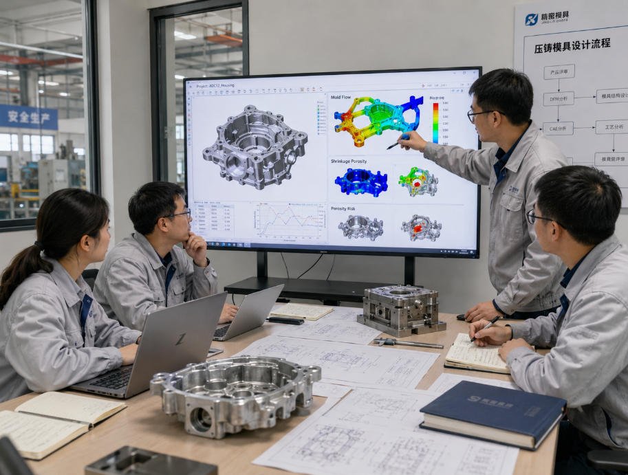
How DFM and Mold Flow Analysis Prevent Defects
The most effective way to reduce die casting defects is identifying risks before tooling production.
A professional DFM review evaluates:
Part Geometry
Including:
- Wall thickness
- Draft angles
- Ribs and fillets
- Machining requirements
Metal Flow Behavior
Mold flow analysis helps engineers evaluate:
- Filling patterns
- Air trap risks
- Cooling performance
- Potential defect locations
Tooling Optimization
Proper tooling design improves:
- Part consistency
- Mold life
- Production stability
Die Casting Defect Prevention Workflow
A reliable OEM manufacturing process follows:
CAD Design Review

↓

DFM Analysis

↓

Mold Flow Simulation

↓

Tooling Optimization

↓

Casting Trial

↓

CMM Inspection

↓

Mass Production
This approach helps reduce:
- Tool modifications
- Production delays
- Quality risks
Die Casting + CNC Post-Machining Quality Control
Die casting creates efficient near-net-shape components.
However, many OEM parts require CNC machining for precision features.
Common CNC operations include:
- Precision holes
- Threads
- Bearing seats
- Sealing surfaces
- Assembly interfaces
CNC machining improves dimensional accuracy, but it cannot repair internal casting defects.
Therefore, defect prevention must begin during:
- Design
- Tooling
- Casting development
FSD Precision combines:
with:
to provide complete OEM manufacturing solutions.
Quality Inspection for Die Cast Components
Quality control verifies:
- Dimensional accuracy
- Material consistency
- Surface quality
- Functional requirements
Inspection methods include:
- CMM measurement
- Dimensional inspection
- Engineering drawing verification
- Visual inspection
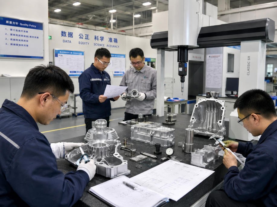
How FSD Precision Prevents Die Casting Defects
FSD Precision supports OEM customers through a complete quality-focused manufacturing process.
Engineering Review
Before tooling:
- Review CAD geometry
- Identify casting risks
- Recommend improvements
Tooling Optimization
Evaluate:
- Mold design
- Metal flow
- Cooling strategy
Production Control
Monitor:
- Casting quality
- CNC machining
- Surface finishing
Final Inspection
Verify:
- Critical dimensions
- Product consistency
- Customer requirements
FAQ
What is the most common aluminum die casting defect?
Porosity is one of the most common aluminum die casting defects.
It is usually caused by:
- Trapped gas
- Poor metal flow
- Uneven solidification
What causes porosity in aluminum die casting?
Common causes include:
- Poor venting
- Turbulent filling
- Incorrect injection parameters
- Uneven wall thickness
What is the difference between gas porosity and shrinkage porosity?
Gas porosity is caused by trapped air or gas during filling.
Shrinkage porosity is caused by uneven metal contraction during cooling.
Both require proper design and process control.
How can manufacturers reduce die casting defects?
Manufacturers reduce defects through:
- DFM analysis
- Mold flow simulation
- Proper tooling design
- Process control
- Quality inspection
Can CNC machining fix die casting defects?
CNC machining can improve:
- Dimensional accuracy
- Threads
- Assembly features
However, internal defects such as severe porosity must be prevented during casting.
How does DFM improve die casting quality?
DFM identifies:
- Wall thickness issues
- Metal flow problems
- Draft angle risks
- Machining requirements
before tooling production begins.
Conclusion
High-quality aluminum die casting components are not achieved only through production control.
They are created through:
- Proper part design
- Effective tooling
- Optimized metal flow
- Stable production processes
- Quality inspection
By understanding common die casting defects and prevention methods, OEM engineers can reduce production risks, improve part reliability and control manufacturing costs.
FSD Precision helps global customers develop reliable die casting solutions through:
- DFM engineering review
- Tooling coordination
- Die casting production
- CNC post-machining
- Surface finishing
- Quality inspection
Ready to improve your die casting project quality?
Upload your CAD files and engineering drawings for a professional DFM review and manufacturing recommendation.
Need help sourcing custom OEM parts?
Send drawings, samples, part numbers, material requirements, quantity, and application details for engineering review.