
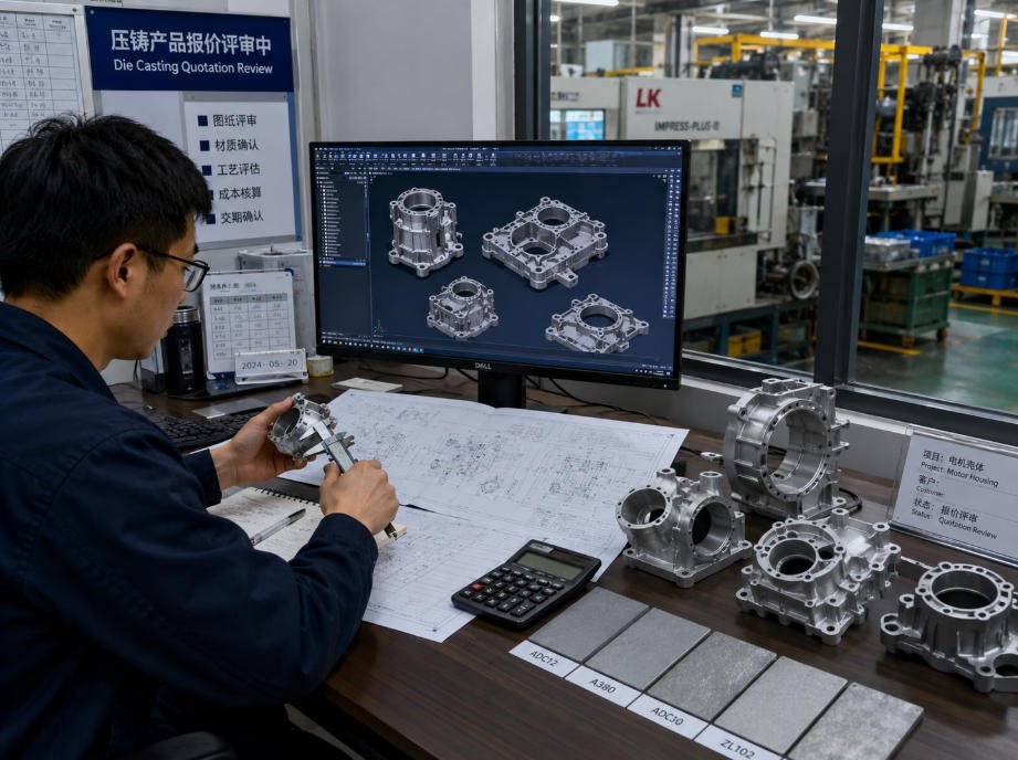
A successful die casting project requires more than a standalone 3D model.
To receive an accurate, production-ready quotation, OEM buyers should provide a complete Technical Data Package (TDP) including:
- 3D CAD files
- 2D engineering drawings
- Alloy specifications
- Estimated Annual Usage (EAU)
- Surface finish requirements
- Critical tolerance requirements
- Application details
A complete technical package allows manufacturing engineers to accurately evaluate:
- Mold tooling requirements
- Casting feasibility
- Material selection
- CNC post-machining needs
- Production costs
An incomplete RFQ often creates additional clarification cycles, extends quotation timelines and forces suppliers to add risk margins due to unclear requirements.
At FSD Precision, we help OEM procurement and engineering teams review technical data packages and develop reliable manufacturing solutions from design evaluation through production.
Learn more about our Custom Die Casting Services.
Why Die Casting Quotes Are Often Delayed
In industrial manufacturing, quotation delays are rarely caused by factory capacity.
They usually happen because important technical information is missing during the initial inquiry.
Common RFQ issues include:
- Providing product photos without accurate dimensions
- Sending a 3D CAD model without a 2D drawing
- Specifying only “aluminum” without an exact alloy designation
- Missing production volume information
- Not defining critical tolerance areas
- Leaving surface finish requirements unclear
For example, an aluminum electronic housing and an aluminum structural bracket may appear similar, but they require different:
- Alloy selections
- Mold designs
- Metal flow strategies
- CNC machining requirements
Providing complete information helps engineers evaluate the project accurately from the beginning.
Building a Complete Technical Data Package (TDP)
A professional die casting RFQ should include several key elements.
1. 3D CAD Files: Defining Part Geometry
A solid 3D CAD model is the foundation of the quoting process.
It allows engineers to evaluate:
- Part geometry
- Part weight
- Wall thickness
- Mold complexity
- Potential manufacturing challenges
Recommended Formats
| File Format | Engineering Purpose |
|---|---|
| STEP / STP | Widely used format for accurate 3D geometry exchange |
| Parasolid (.X_T) | Reliable solid model transfer |
| IGES (.IGS) | Useful for surface data exchange |
| Native CAD Files | Helpful when design history is required |
STEP and STP files are commonly preferred because they work across many CAD/CAM platforms.
Why STL Files Are Usually Insufficient
STL files are mesh-based formats mainly used for:
- Visual models
- 3D printing
They usually do not provide:
- True solid geometry
- Thread information
- Feature history
- Manufacturing details
For precision die casting projects, STEP or native CAD files are usually more suitable.
2. 2D Engineering Drawings: Defining Manufacturing Requirements
If the 3D model defines the shape of the component, the 2D drawing defines the engineering requirements.
A complete drawing should include:
Critical Tolerances
Identify areas requiring:
- Precision alignment
- Assembly accuracy
- Functional fits
Thread Specifications
Include:
- Thread size
- Pitch
- Depth
- Thread standard
Example:
- M6 × 1.0
- 1/4-20 UNC
Surface Requirements
Specify:
- Surface roughness
- Cosmetic areas
- Sealing surfaces
Datum References
Clear datums help support:
- CNC fixturing
- CMM inspection
- Dimensional verification
For OEM components, 2D drawings are essential because many precision features are achieved through secondary machining after casting.
3. Material Requirements: Selecting the Right Alloy
Material selection affects:
- Part performance
- Tool design
- Surface finishing
- Production cost
Aluminum Die Casting
Common alloys:
- A380
- ADC12
- A360
Suitable for:
- Lightweight structures
- Heat dissipation components
- Industrial housings
- Automotive parts
Zinc Die Casting
Common alloys:
- Zamak 3
- Zamak 5
- ZA series
Suitable for:
- Small precision components
- Thin-wall parts
- Decorative hardware
- Complex geometries
Magnesium Die Casting
Common alloys:
- AZ91D
- AM60B
Suitable for:
- Weight-sensitive applications
- Electronics housings
- Lightweight structural components
Related resource:
Aluminum Die Casting vs Zinc Die Casting: Which Material Is Right for Your Part?
4. Estimated Annual Usage (EAU) and Tooling Strategy
Production volume plays a major role in die casting economics.
Unlike CNC machining, die casting requires dedicated tooling.
EAU helps engineers determine:
- Mold configuration
- Number of cavities
- Automation requirements
- Expected tooling investment
Low Volume Projects
For prototypes or uncertain designs:
- CNC machining
- Prototype tooling
may be more practical.
Medium and High Volume Production
For long-term production programs:
- Multi-cavity tooling
- Optimized production processes
can reduce unit cost.
Understanding annual demand helps manufacturers recommend the right tooling strategy.
5. Tolerances and CNC Post-Machining Requirements
Die casting is excellent for producing near-net-shape components.
However, some functional features require secondary CNC machining.
Common examples:
- Bearing bores
- Internal threads
- Assembly surfaces
- Precision holes
Standard casting tolerances are usually wider than CNC machining capabilities.
For critical features, customers should clearly identify machining requirements on the 2D drawing.
FSD Precision combines die casting with CNC Machining Services to achieve tighter control on critical machined features.
6. Surface Finish Requirements
Surface treatments affect:
- Appearance
- Corrosion resistance
- Cost
- Final dimensions
Common finishing options include:
- Powder coating
- Liquid painting
- Sand blasting
- Electroplating
- Chemical treatments
For more finishing solutions, visit:
The Master Die Casting RFQ Checklist
Before submitting your technical package, confirm the following:
| Required Information | Why It Matters |
|---|---|
| 3D CAD Model | Evaluates geometry and tooling requirements |
| 2D Engineering Drawings | Defines tolerances and inspection needs |
| Alloy Specification | Determines material and process planning |
| Estimated Annual Usage (EAU) | Determines tooling strategy |
| Surface Finish Requirements | Plans secondary processing |
| Critical Dimensions | Identifies machining requirements |
| Application Details | Helps evaluate functional requirements |
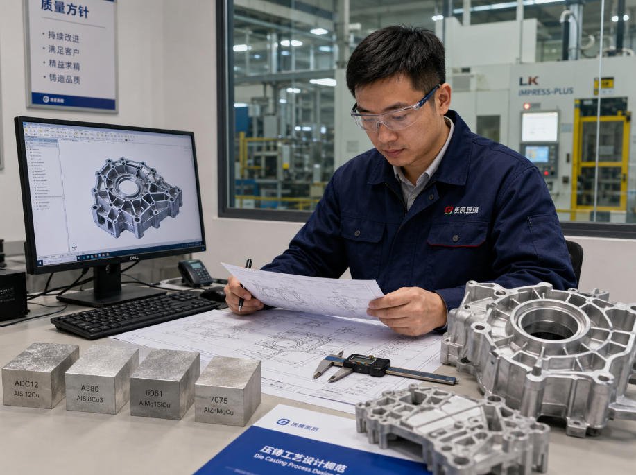
How FSD Precision Reviews Die Casting RFQs
At FSD Precision, RFQ evaluation goes beyond calculating a price.
Every project is reviewed from a manufacturing perspective.
Design for Manufacturability (DFM) Review
Our engineers evaluate:
- Wall thickness
- Draft angles
- Part geometry
- Potential casting risks
This helps customers avoid costly redesigns before tooling investment.
Tooling Assessment
We review:
- Mold complexity
- Production requirements
- Manufacturing approach
Secondary Process Planning
We evaluate:
- CNC machining
- Surface finishing
- Inspection requirements
Why Choose FSD Precision?
FSD Precision supports OEM customers with complete manufacturing solutions from engineering review to final delivery.
Our capabilities include:
- Die casting evaluation
- Aluminum and zinc die cast parts
- Tooling coordination
- CNC post-machining
- Surface finishing
- Quality inspection
- Export support
Our process:
CAD Design
↓
DFM Review
↓
Tooling
↓
Casting
↓
Machining
↓
Finishing
↓
Inspection
FAQ
What files are required to receive a die casting quote?
A complete RFQ should include:
- 3D CAD files
- 2D drawings
- Material requirements
- Production volume
- Surface finish requirements
- Critical tolerances
Do I need to own a mold before requesting a quote?
No.
FSD Precision can evaluate your design requirements and recommend the appropriate tooling approach based on production goals.
How does Estimated Annual Usage affect tooling cost?
EAU influences:
- Mold design
- Cavity selection
- Automation level
- Unit cost calculation
Higher production volumes usually allow tooling costs to be distributed across more parts.
Can die cast components achieve tight tolerances?
Die casting provides near-net-shape components, but critical features such as bearing seats, threads and precision fits usually require CNC post-machining.
How early should DFM review begin?
DFM review should begin during the CAD design stage, before tooling production.
Early review helps identify:
- Casting risks
- Machining requirements
- Cost-saving opportunities
Conclusion
A successful die casting project starts with a complete technical package.
Providing accurate CAD files, engineering drawings, alloy specifications, annual usage and tolerance requirements gives manufacturers the information needed to develop a reliable production strategy.
FSD Precision works with global OEM engineering and procurement teams to reduce sourcing delays and deliver turnkey die casting solutions from tooling to finished components.
Ready to start your die casting project?
Send your CAD files and technical requirements to FSD Precision for engineering review and quotation.
Need help sourcing custom OEM parts?
Send drawings, samples, part numbers, material requirements, quantity, and application details for engineering review.